Domus40 HA - Part 2 - Teardown
• goncalomb • home-automation
Domus40 HA series: Part 1 / Part 2 / Part 3 (TBA).
Here we go, let’s take apart some Domus40 devices.
Gateway
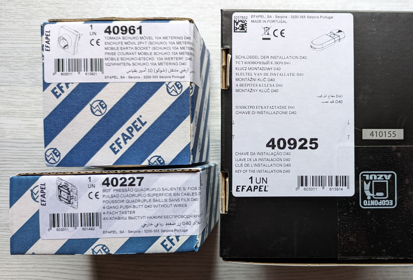
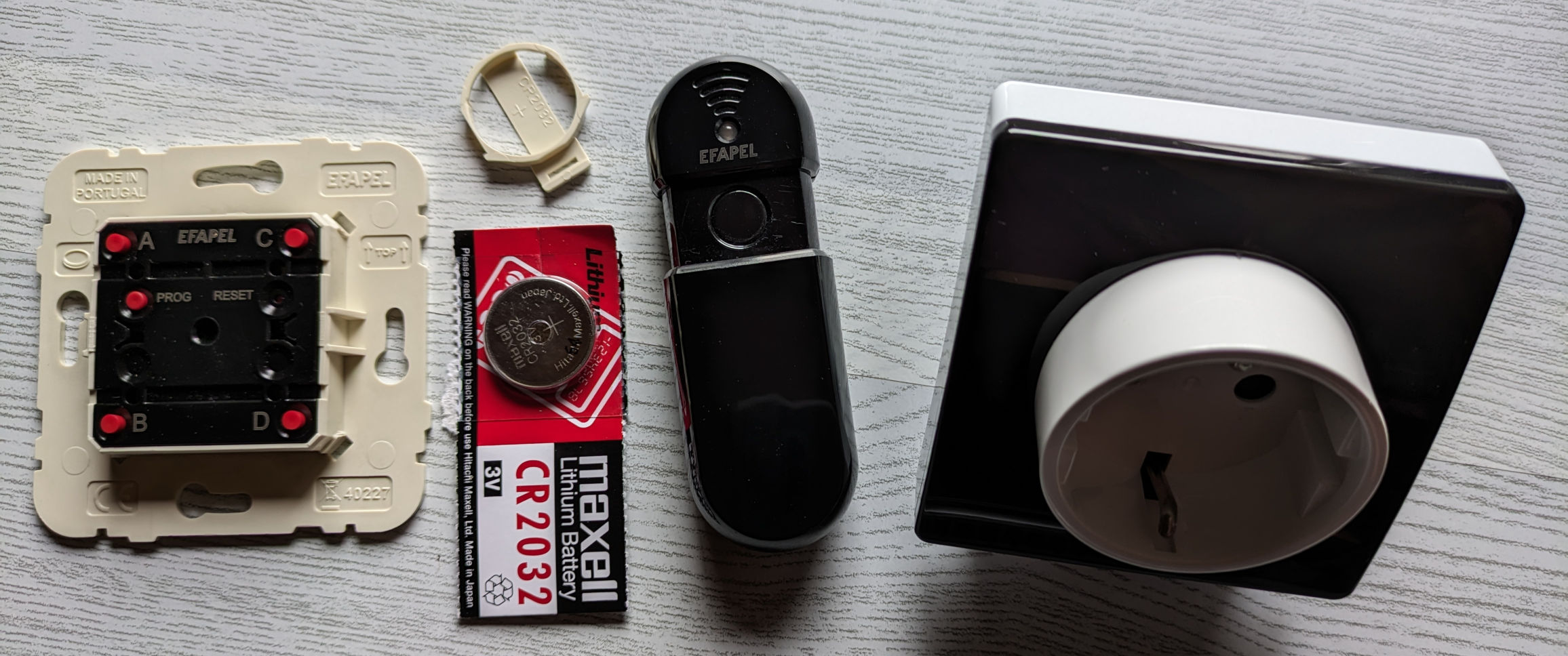
Also known as Installation Key (ref. 40925).
Starting with the gateway, the first thing I did was plug it into my Linux machine. Here’s the dmesg output:
[23756.561987] usb 1-5: new full-speed USB device number 10 using xhci_hcd
[23756.712637] usb 1-5: New USB device found, idVendor=0451, idProduct=16c8, bcdDevice= 1.00
[23756.712651] usb 1-5: New USB device strings: Mfr=1, Product=2, SerialNumber=0
[23756.712657] usb 1-5: Product: CC2538 USB CDC
[23756.712661] usb 1-5: Manufacturer: Texas Instruments
[23756.809695] cdc_acm 1-5:1.0: ttyACM0: USB ACM device
[23756.809771] usbcore: registered new interface driver cdc_acm
[23756.809774] cdc_acm: USB Abstract Control Model driver for USB modems and ISDN adapters
We get some good information, it’s based on a TI CC2538 IEEE 802.15.4 IC and exposes a USB serial port. Not unexpected for a Zigbee gateway, but it’s an older IC, newer alternatives are available (see TI Zigbee Selection Guide, 2018).
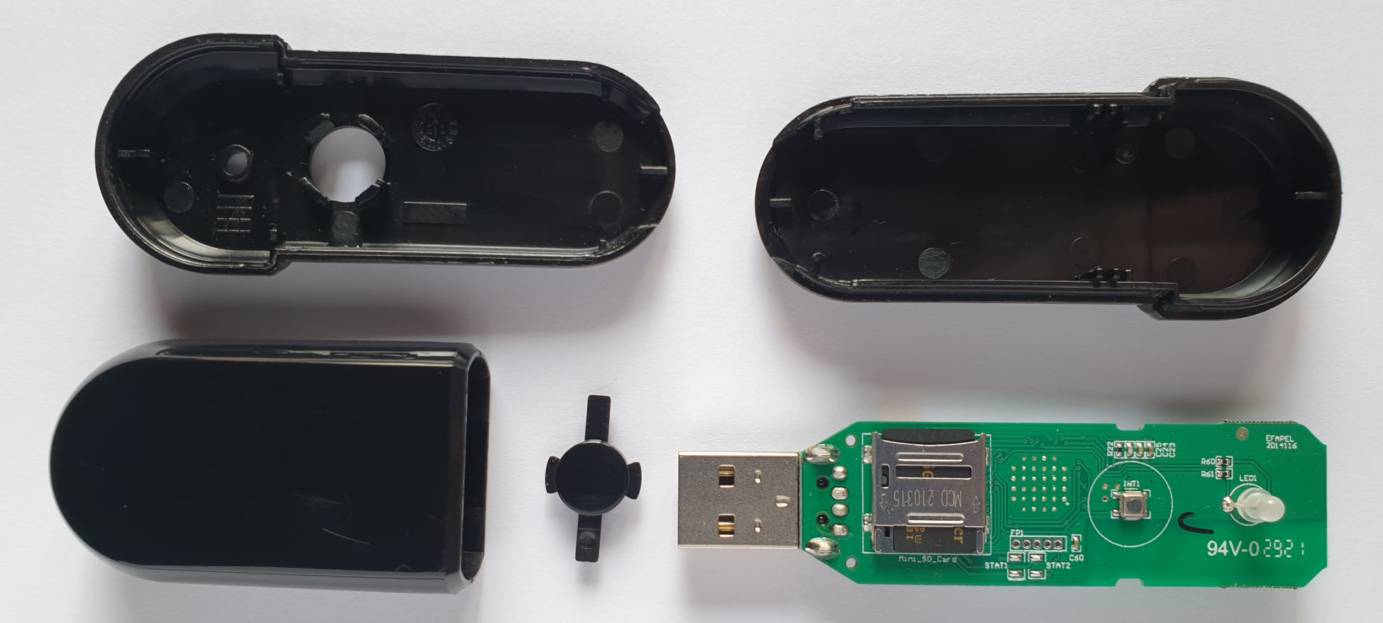
Good construction, but also very hard to take apart without breaking, I had to shim it at the slide point from both sides. It’s intact but not without scratches.


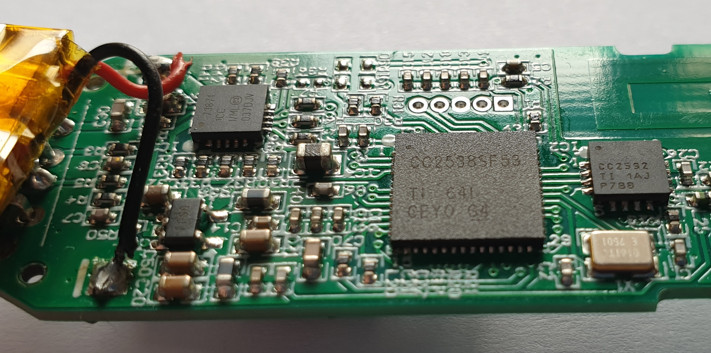
As expected we have the CC2538SF53 as the main IC with a CC2592 RF front end and MCP73871 for battery management. Having a built-in battery is definitely the defining feature of this gateway.
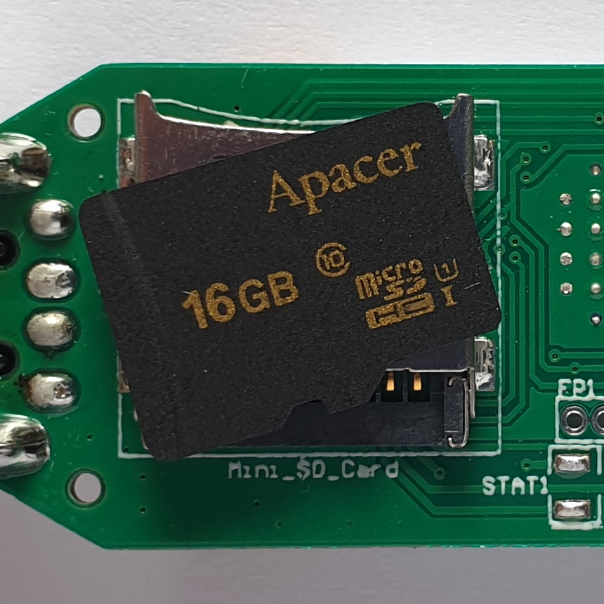
The MicroSD card
The MicroSD card was a surprise, but I think it makes sense. I suspect that the SD card holds the Zigbee network information to allow the gateway to work while disconnected from the host (PC).
The card contains a FAT32 partition, with a single System Volume Information directory. So it was connected to a Windows PC at some point, it’s dated April 2022.
4A21-0000:
total 32
drwxr-xr-x 2 32768 2022-04-13 12:37:26.000000000 +0100 System Volume Information

4A21-0000/System Volume Information:
total 64
-rw-r--r-- 1 76 2022-04-13 12:37:28.000000000 +0100 IndexerVolumeGuid
-rw-r--r-- 1 12 2022-04-13 12:37:26.000000000 +0100 WPSettings.dat
I tried pairing it with another device to see if something changed but was unable to make it work. This is something to explore in the future.
The USB serial port
Something to also explore later is the serial port and its unknown protocol. I tried using Zigbee2MQTT, but it could not communicate with the gateway. I know that Zigbee2MQTT uses TI’s Z-Stack Monitor and Test API / Z-Stack ZNP, but I’m not familiar with these APIs at all. It remains to be seen if I can get it to work using the stock firmware.
Push buttons
Also known as Wireless 4-Gang Push Button (ref. 40227).
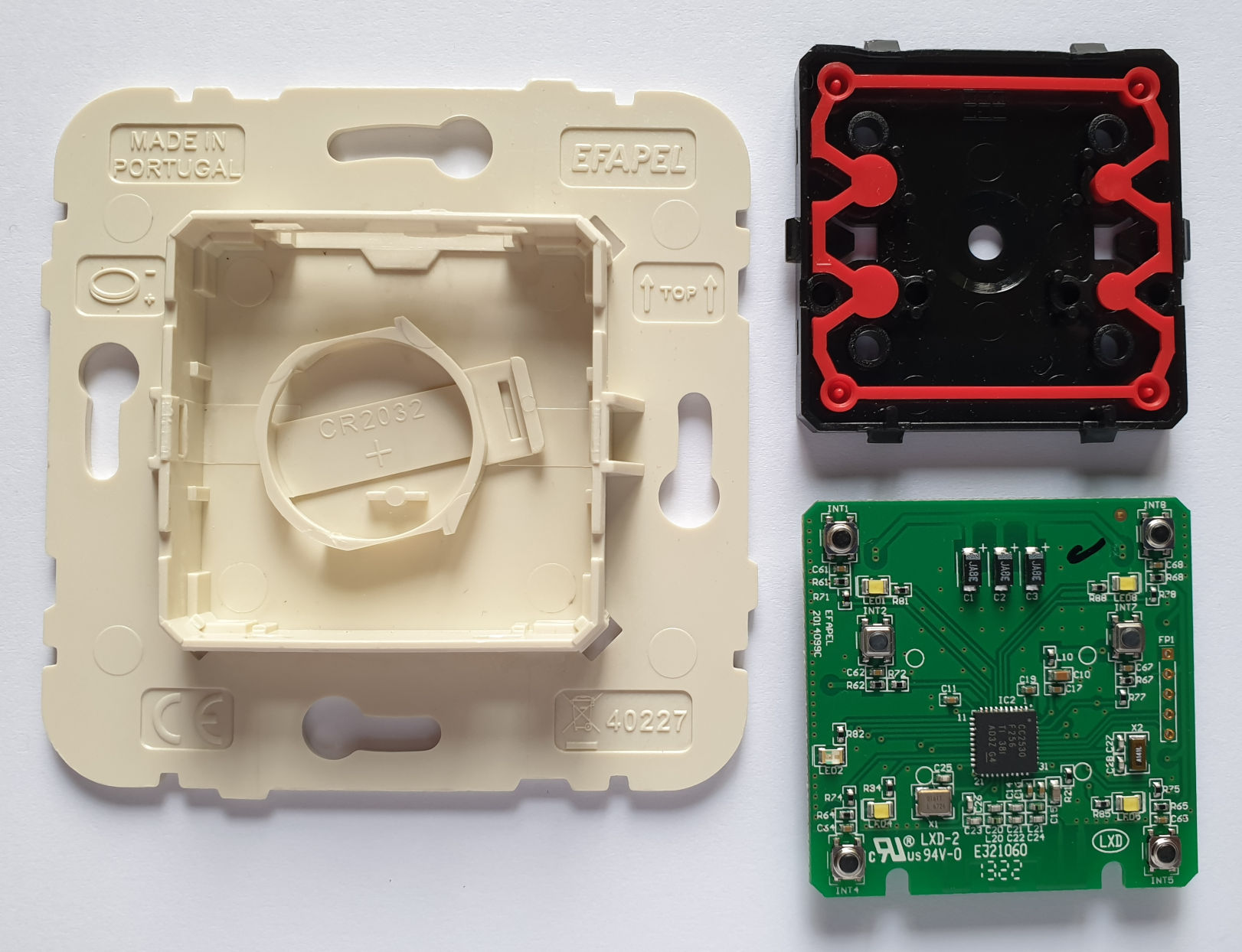
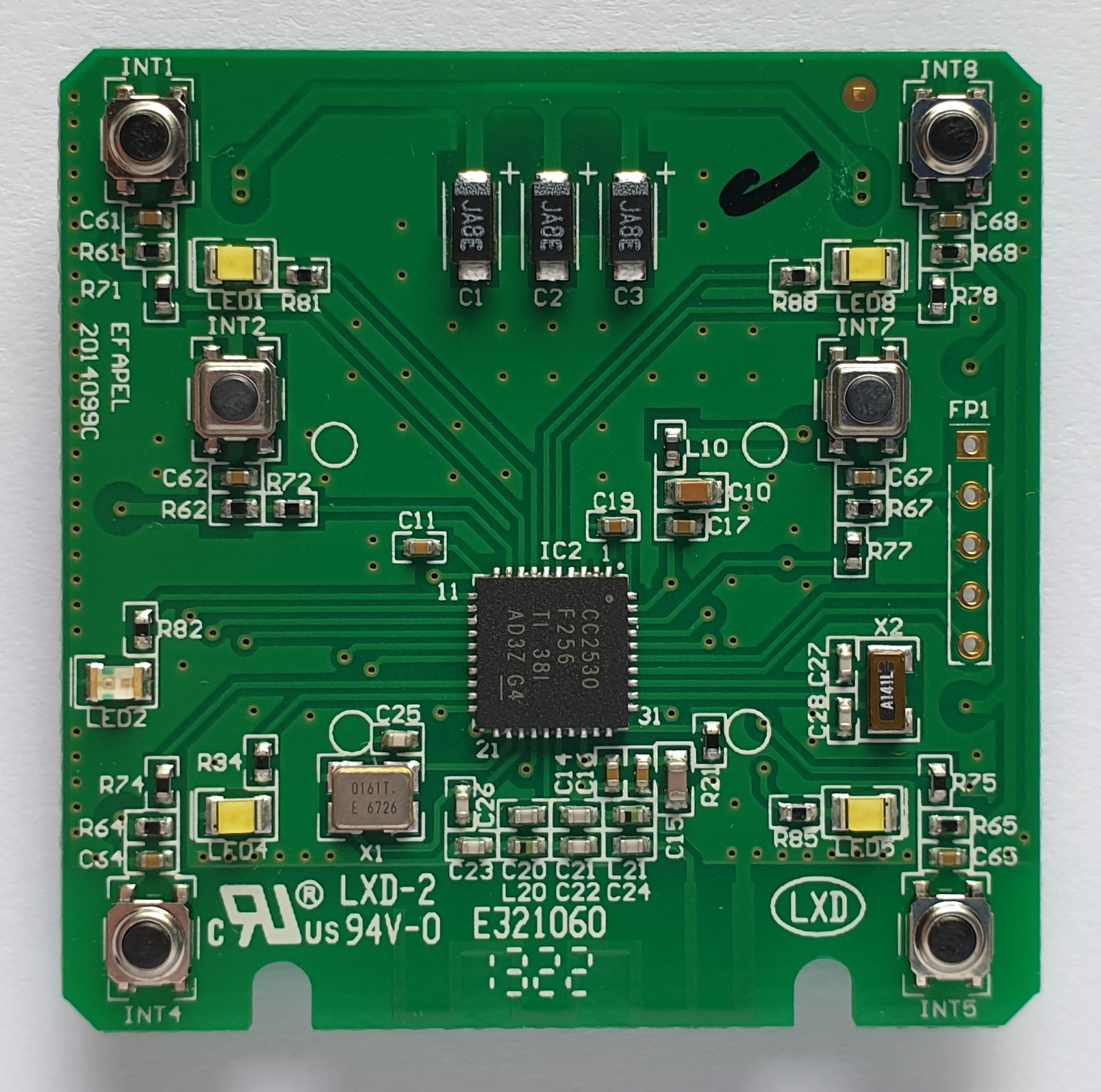
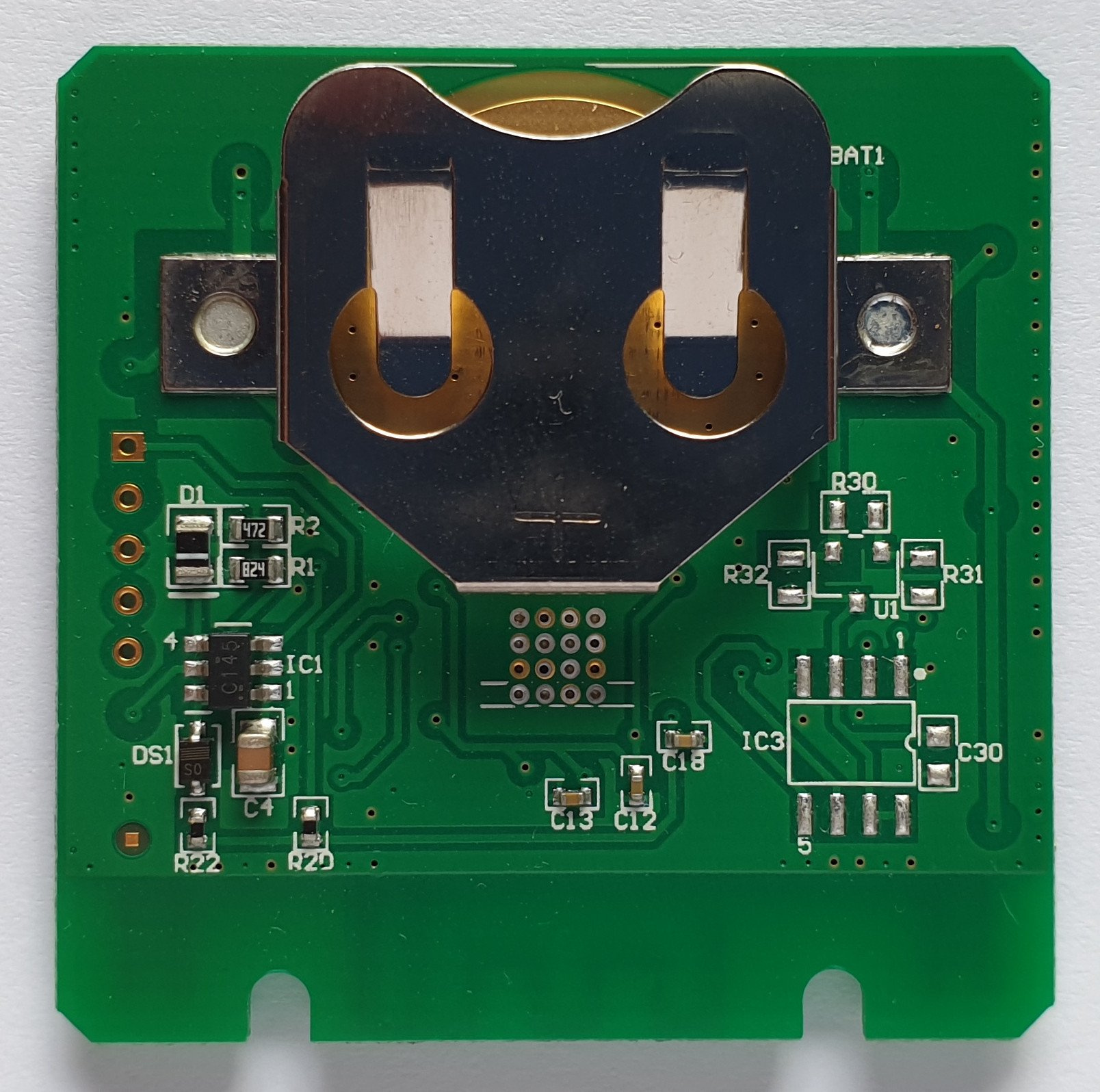
It’s based on a CC2530 IC, powered by a coin cell. Nothing special, similar to other Zigbee buttons, well constructed. Some pads are not populated.
Connecting to Zigbee2MQTT
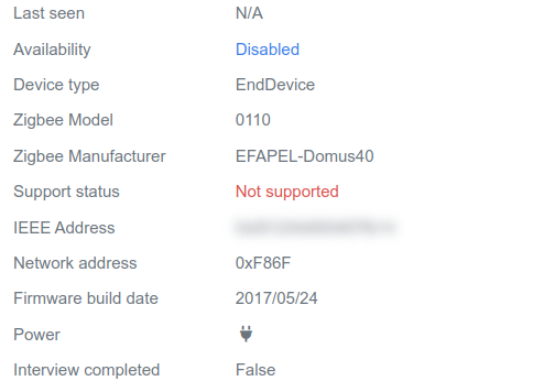
As expected, it’s not supported by Zigbee2MQTT out of the box, this should be just a missing configuration. But we get some information.
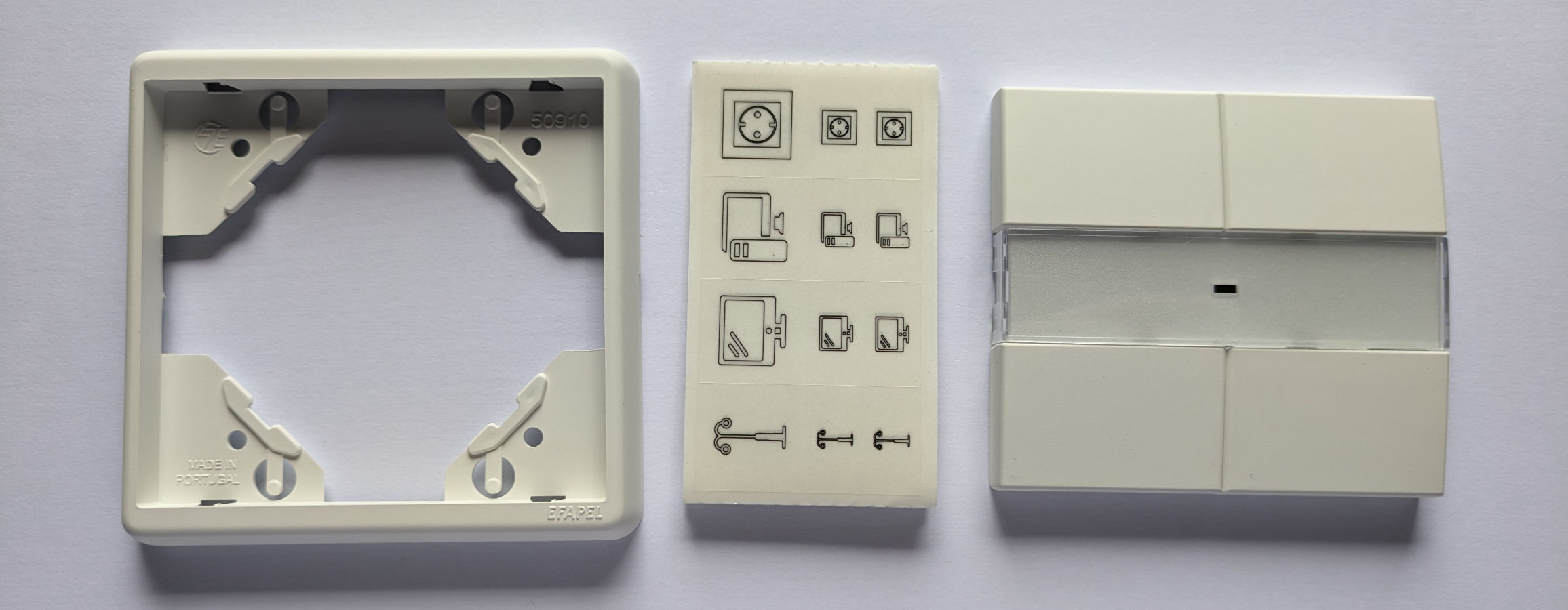
Cover
Just as a side note, these buttons are made to be used with a cover, sold separately. They can be made to match other switches around the house. But they also work fine as a portable device.
Smart plug
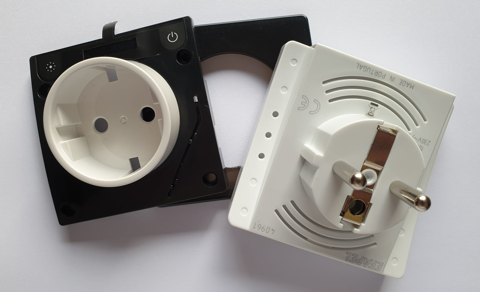
Also known as Mobile Schuko Socket 10A with Metering (ref. 40961).
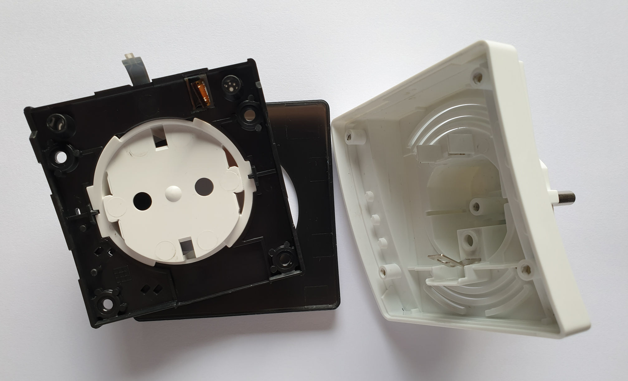
Again, good construction but hard to take apart. The screws are only visible after removing the front bezel.
An internal metal tab for the earth connection broke after I bend it to remove the PCB. I removed the earth contact to avoid future issues, if I end up using this plug it will be only for testing or low-power stuff without an earth connection.

A small piece of PCB material was loose inside (see previous image), not broken from the main PCB.
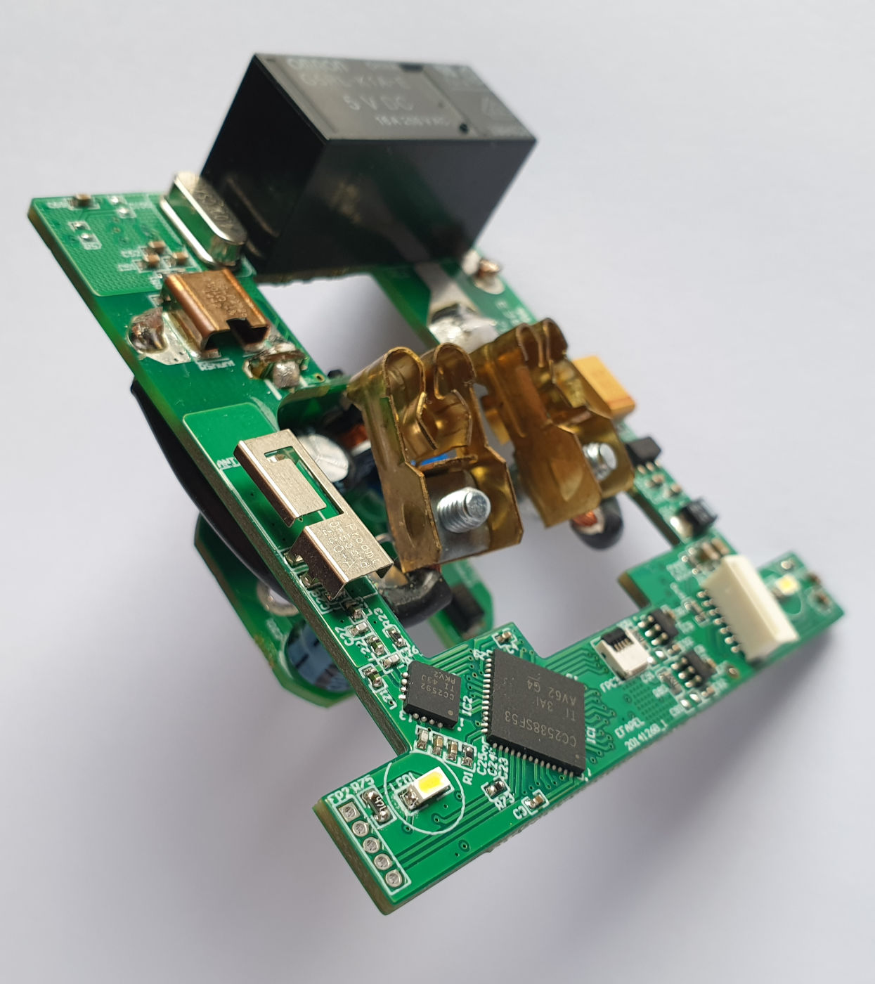
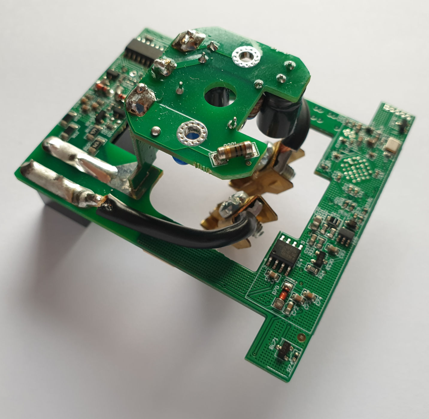
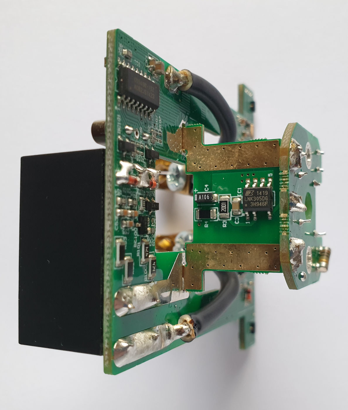
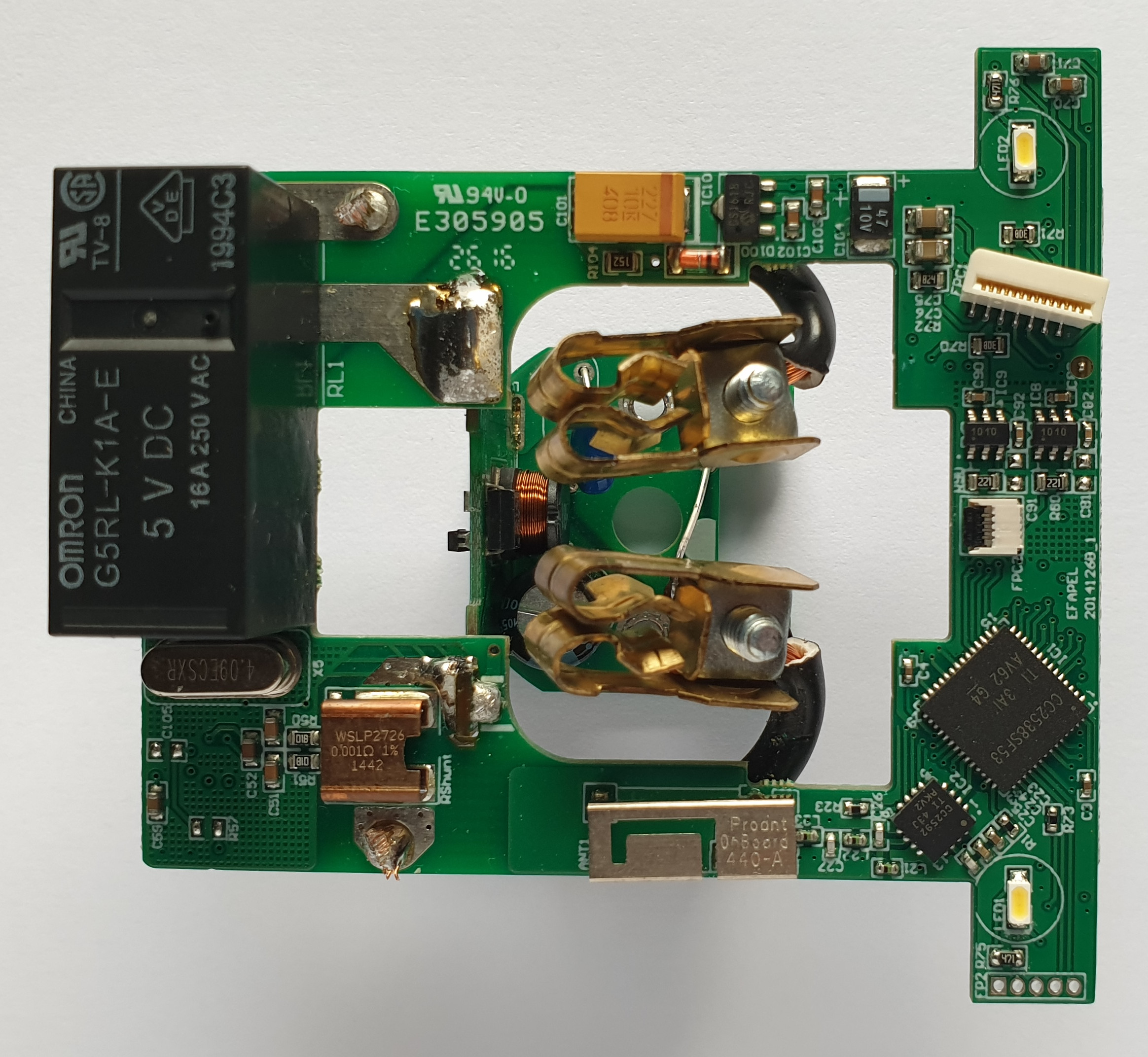
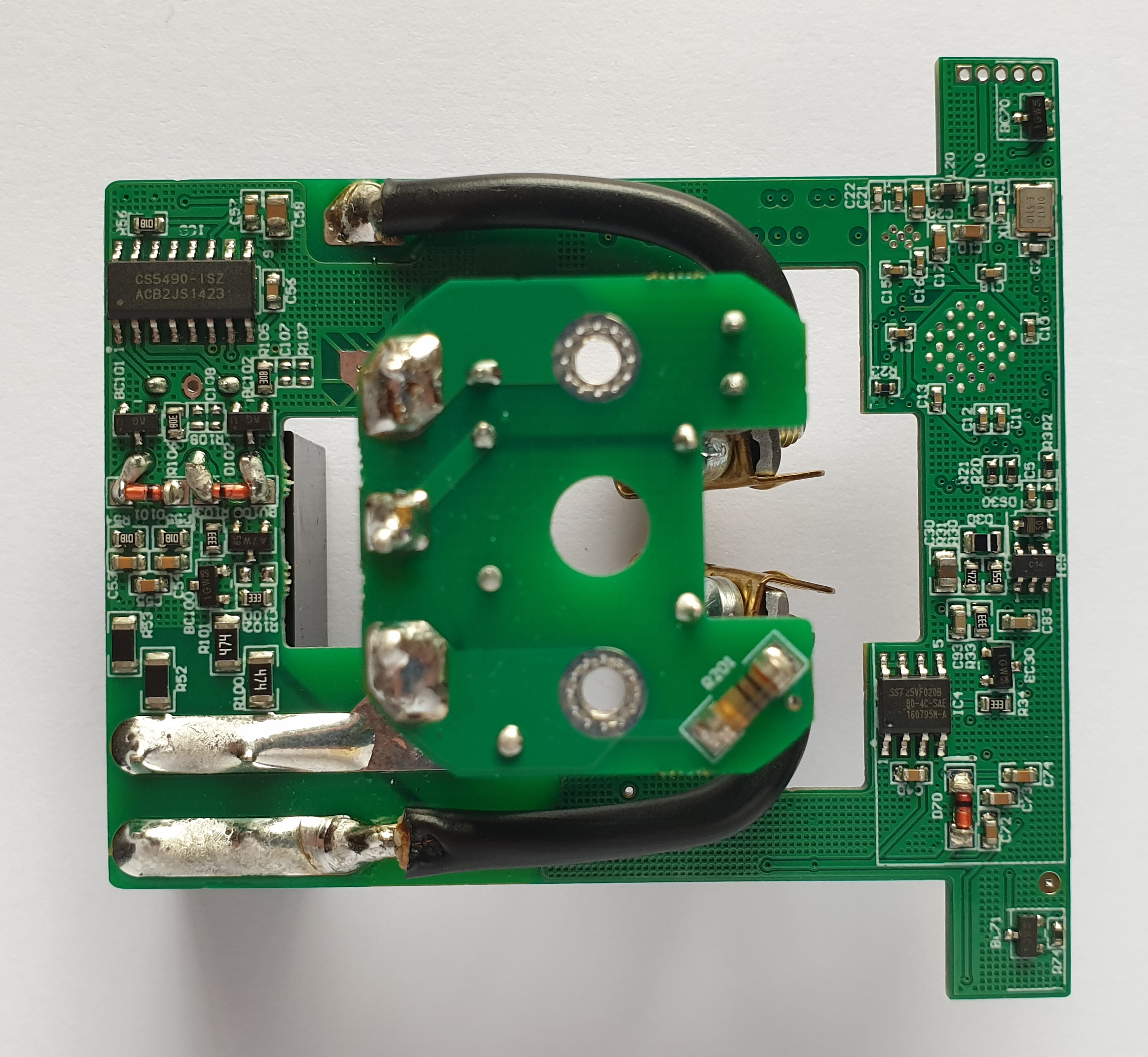
It uses a very interesting layout with 3 PCBs to make use of every bit of space. It’s probably not a cheap device to manufacture (the final price is also not cheap). The main PCB is also multilayer.
The power supply for the low-voltage circuit it’s inside the plug connector on the 2 smaller PCBs, it’s a non-isolated design using an LNK302DG IC.
It uses the same main IC as the gateway, a CC2538SF53 with a CC2592 RF front end. This is expected, being a mains-powered device, it also acts as a Zigbee router not just an end device. The other 2 ICs are an SST25VF020B serial flash and CS5490-ISZ for power measurement.
As with the other devices, the debug header is exposed. But it’s not safe to use while powered by AC because of the non-isolated design.
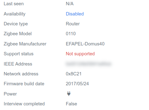
Connecting to Zigbee2MQTT
Not supported by Zigbee2MQTT at the moment, the same as the push buttons.
Are these old designs?
I noticed that these devices appear a few years old, even though they were first released in late 2021.
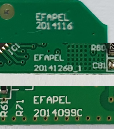
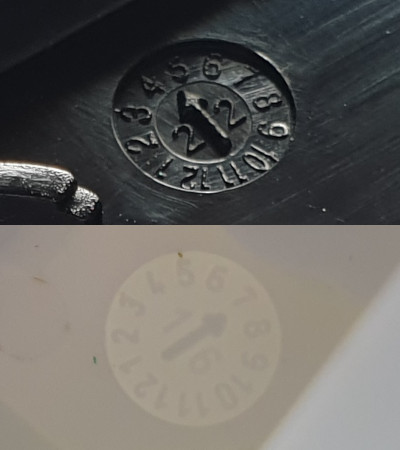
The PCBs, according to the markings, were possibly designed sometime in 2014, which also explains the use of older ICs. Then we have some plastics from 2016 and 2022, some firmware from 2017, and the filesystem on the gateway SD card is dated 2022.
So the gateway that I have is from last year, but the other devices appear to be older. The coin cell that came with the buttons is almost expired (12/2023). Weird.
What’s Next?
Getting these devices connected with Zigbee2MQTT is my main goal.
The gateway is by far the most interesting device. I would like to retain the function of pairing devices while away from the host (PC), which probably requires keeping the stock firmware. Knowing the serial port protocol is key make it work with Zigbee2MQTT and it will require some research on my part (I don’t have the Home Server, which is the official way to use the gateway, see part 1). Let’s hope it uses some standard TI API (Z-Stack ZNP?).
The other 2 devices can already be semi-recognized by Zigbee2MQTT, they might need some extra configuration, but should not require custom firmware.
Updating the firmware would be nice. But that’s probably done automatically by the Home Server. EFAPEL does not publish the firmware on their website and discovering some unknown repository URL without inspecting the Home Server is probably impossible.
I have no affiliation with EFAPEL, all opinions are my own.
Domus40 HA series: Part 1 / Part 2 / Part 3 (TBA).
