How to fix a LCD TV (the bad way)
• goncalomb • electronics,repair,lcd
This serves to document my attempt at extending the life of a dying LCD TV. It is not an essay on how LCD panels work or on how to fix them but provides some general information. I’m not an expert, as we’ll see.
I’ve done some LCD repairs in the past, but they only involved fixing the power supply. In those cases, the problem is easy to identify (blown component/fuse or old capacitors etc.). But not this time.
We have this TV that developed an overall purple tint which apparently is quite common on some LG TVs. A quick search identifies the problem as a faulty backlight, and replacement backlight LED strips are available. “I can easily fix that.” so I thought…

Cracking it open
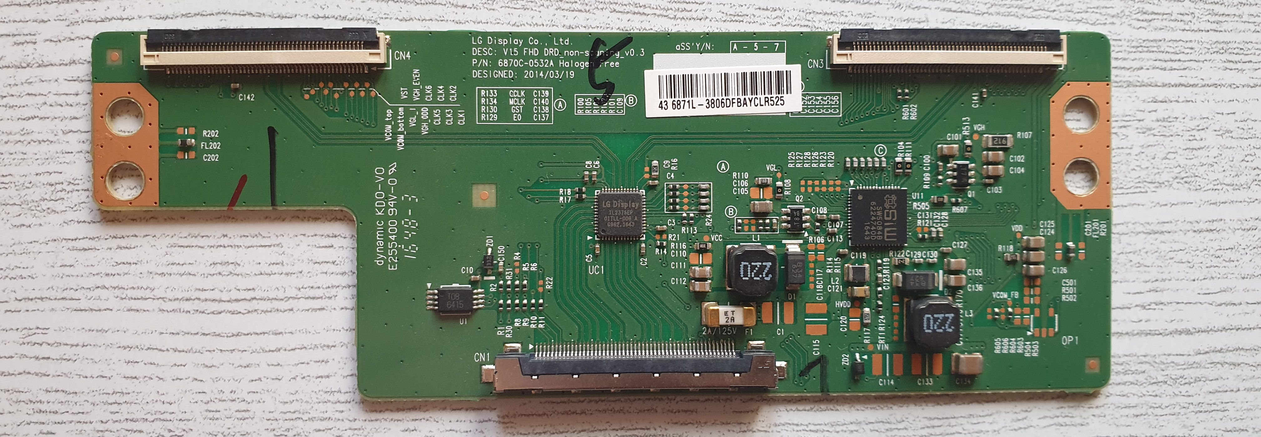
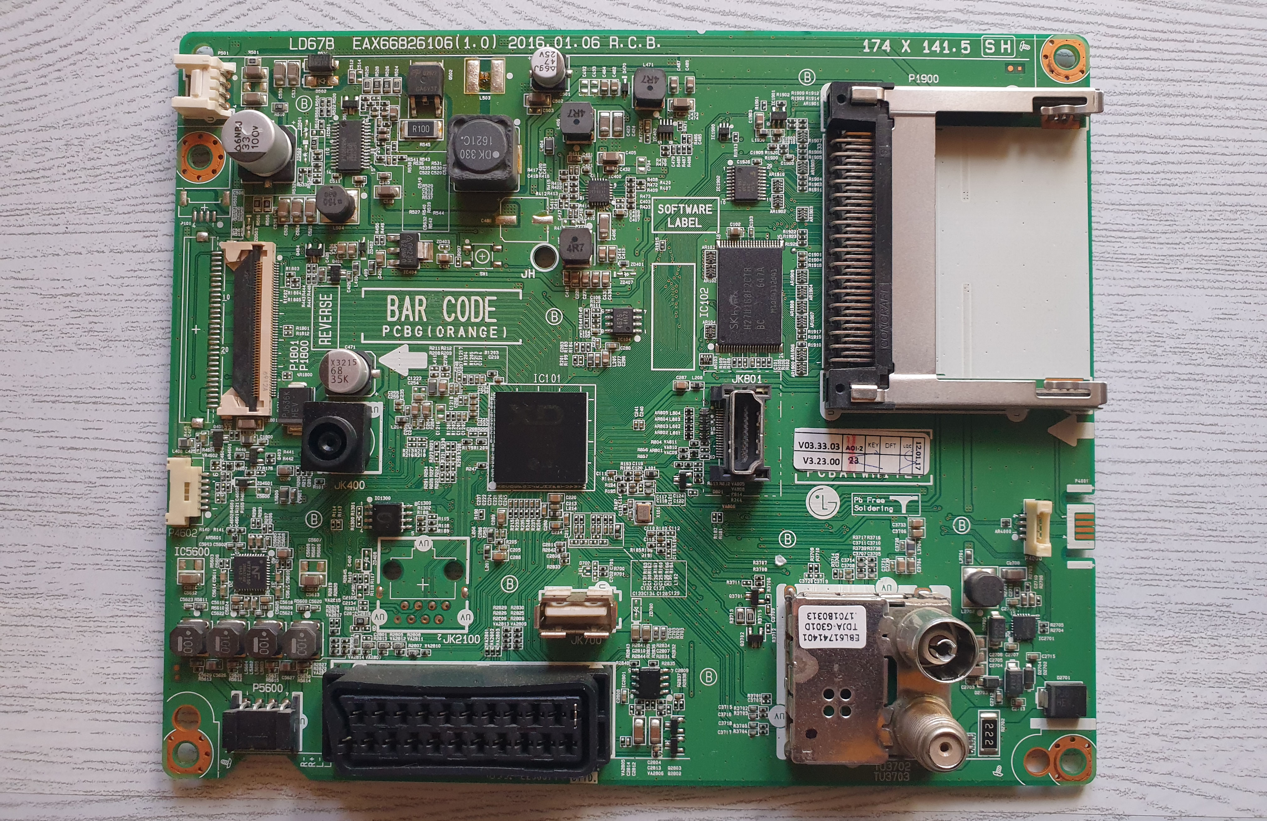
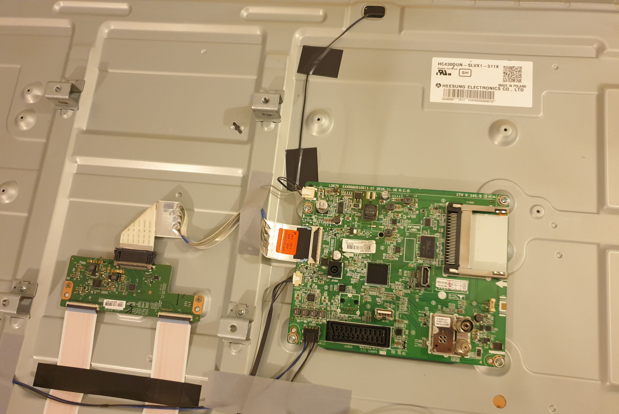
I started by disassembling the TV. After removing the back cover I’m presented with some lovely PCBs, the main board on the right and the T-CON (timing controller) board on the left. No power supply board on this particular model. It uses an external power brick (good, one less way to kill myself).
This is when it starts to go wrong. I had never actually removed an LCD panel this big from the housing (required to access the backlight). Without really looking at how it’s done, I just start unscrewing the bezel and trying to separate it from the rest, with the panel face down. Big mistake. What you are supposed to do is to remove everything from the back (PCBs, speakers etc.) and flip it over to remove the panel from the front.
Well, after doing that and removing the bezel properly… I had cracked the panel, that’s it, game over…
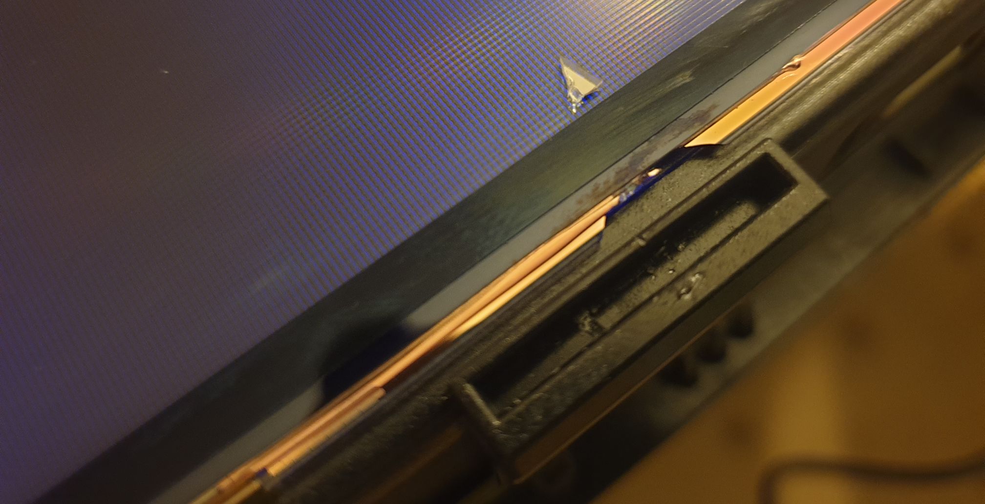
Assessing the damage
Of course, I connected the panel to see the damage.
I’m presented with some weird behavior where the image oscillates between good and bad at fixed intervals but without extra apparent damage. I was expecting some damaged lines of pixels at the point of the crack.
The fact that the image was still intermittently good and I see no other damage gave me some hope. I’m left thinking that this new problem might not be related to the crack, and maybe I zapped the T-CON board. So I ordered another one to test (these are cheap on eBay, reclaimed from old TVs).
It arrives, it’s a complete match, but it exhibits the same problem.
Time to dig further
At this point, I had some general knowledge about how LCDs worked, I knew about the T-CON board and its relationship with the main board, and I had some idea of how the individual sub-pixels of the panel worked to filter the backlight and create an image.
But more research was required.
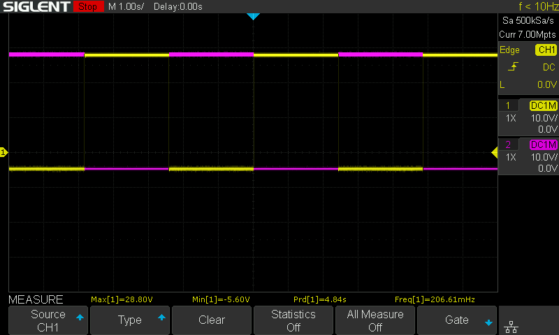
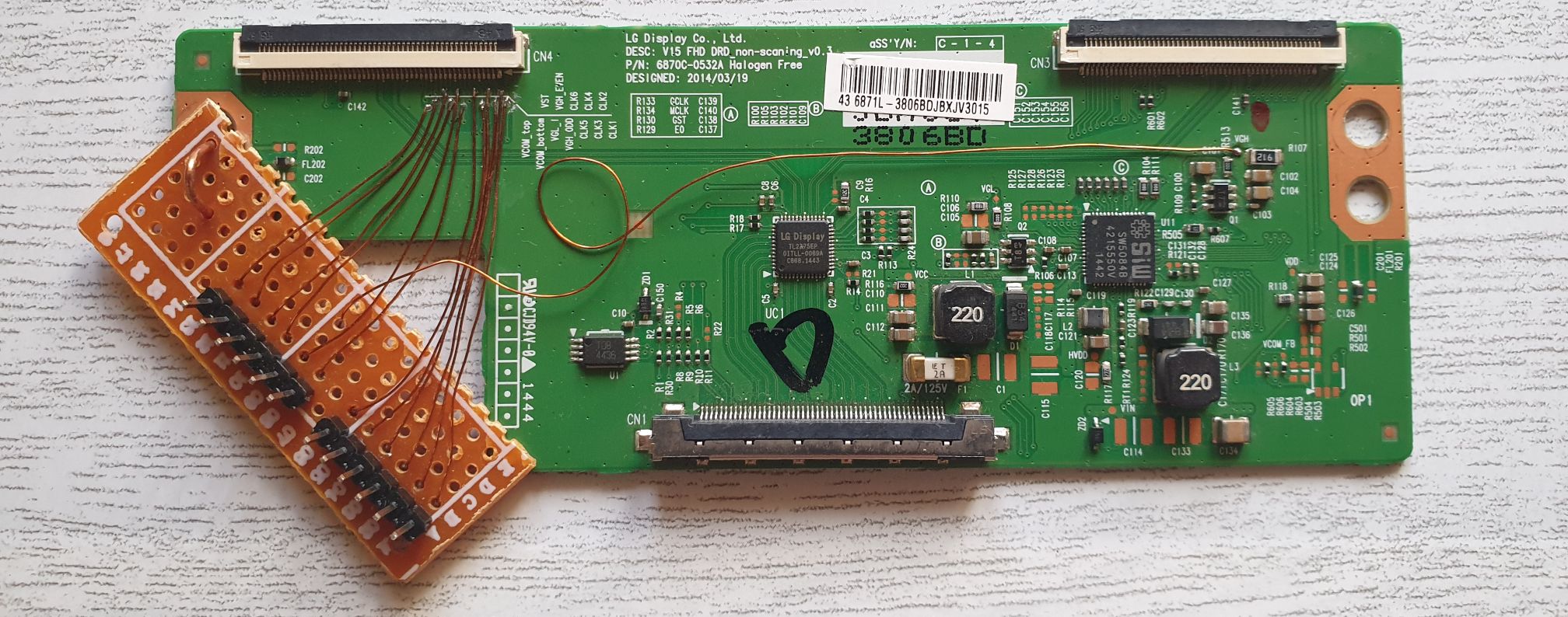
I started by soldering a pin header to some test pads on the T-CON board to inspect some signals with the oscilloscope. Quickly I found that two pads labeled VGH_ODD and VGH_EVEN had square wave signals (opposing phases) with the same periodic timing as the new flickering issue. These are clearly related.
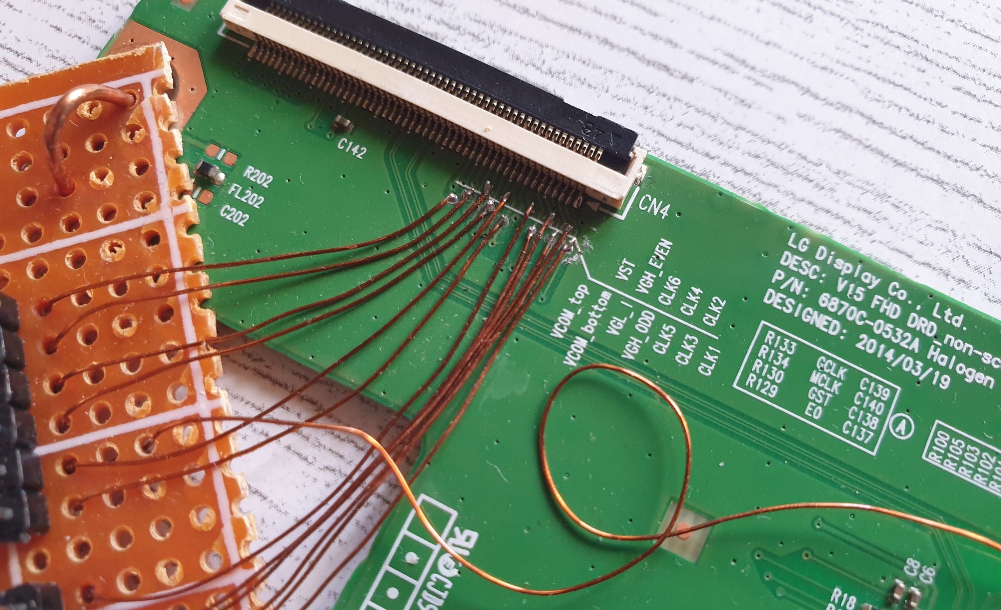
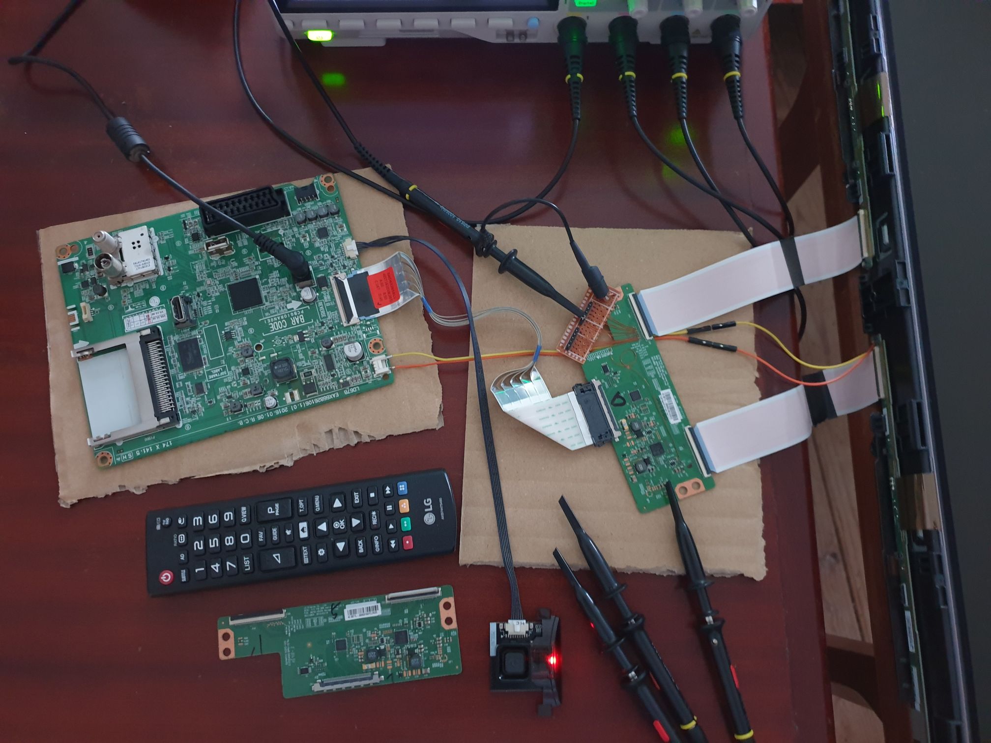
I searched some patents (VGH LCD) to try to understand these signals. And found a good technical video explaining how the signals work.
So this voltage (VGH) is used to drive the gate of panel transistors. But why two signals? See Conclusion.
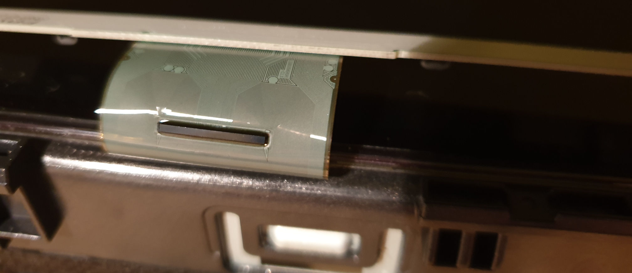
Well, seeing that the problem was not the T-CON board (the signals themselves are good), the issue must be on the panel itself. The panel has a small PCB and some COFs (these are impossible to replace without specialized machinery). I ended up not inspecting anything else on the panel.
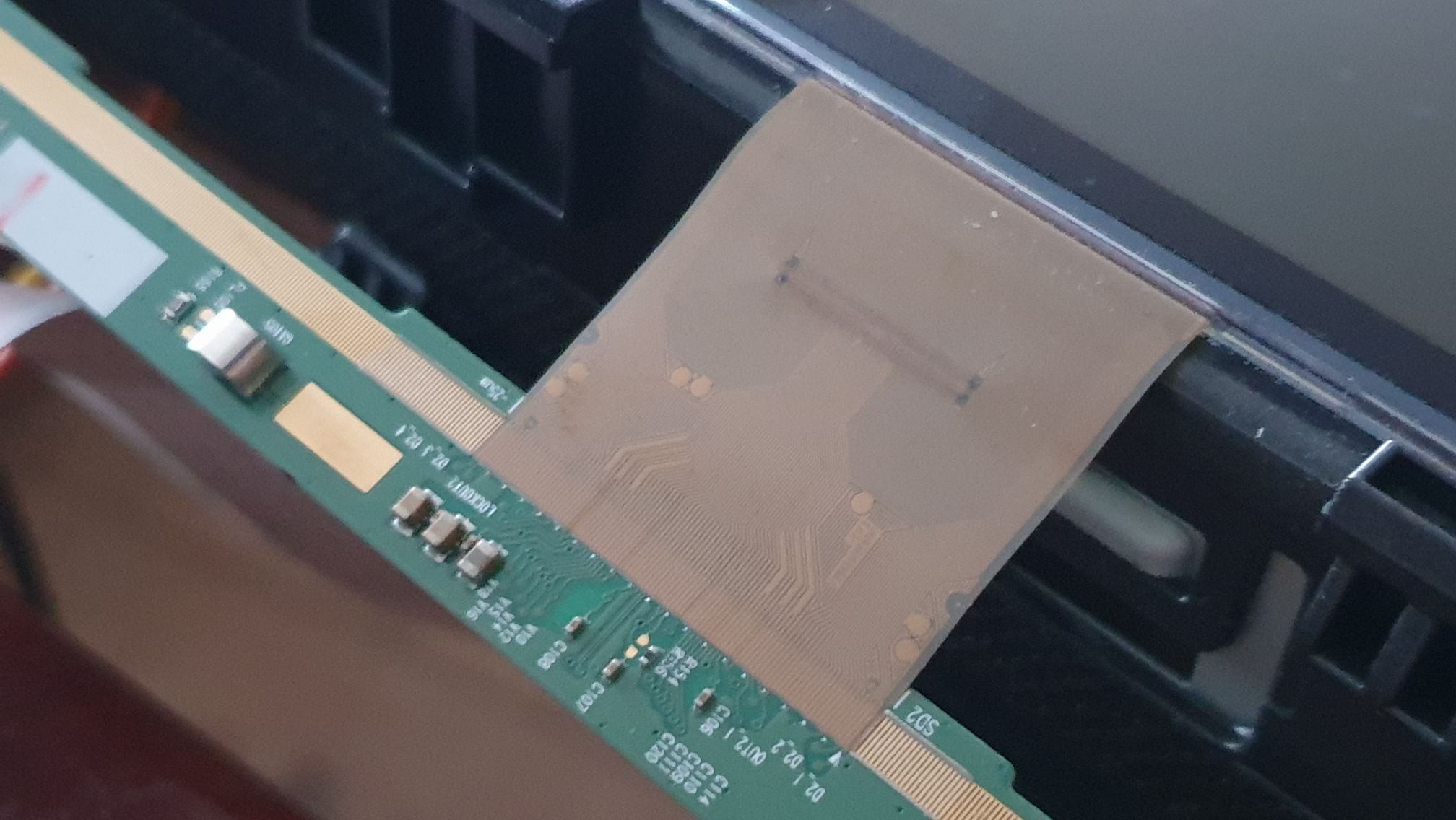
I just tried the obvious solution: if the image is good when VGH_EVEN is HIGH and VGH_ODD is LOW and not the other way around, why not tie VGH_EVEN to HIGH permanently?
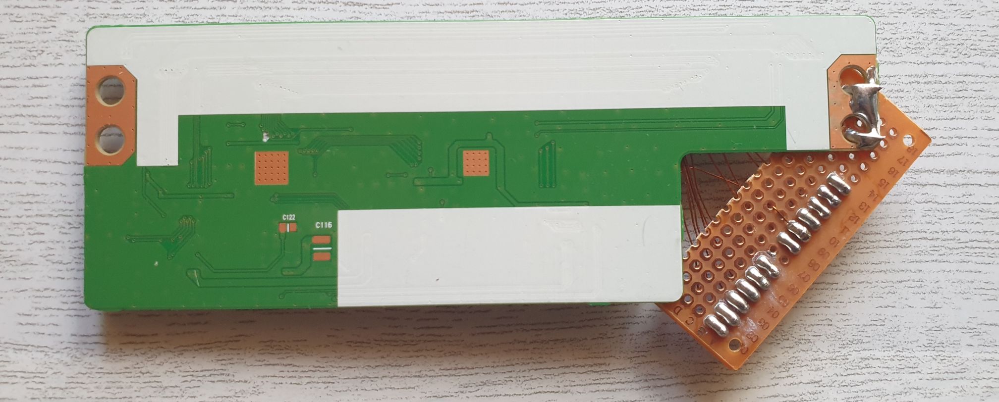
Well, that’s what I did. The board also has a pad called VGH (the HIGH level of the square waves). I just cut the VGH_ODD and VGH_EVEN traces and connected VGH_EVEN to VGH (and left VGH_ODD floating, probably not wise).
And it worked!

Addressing the original problem
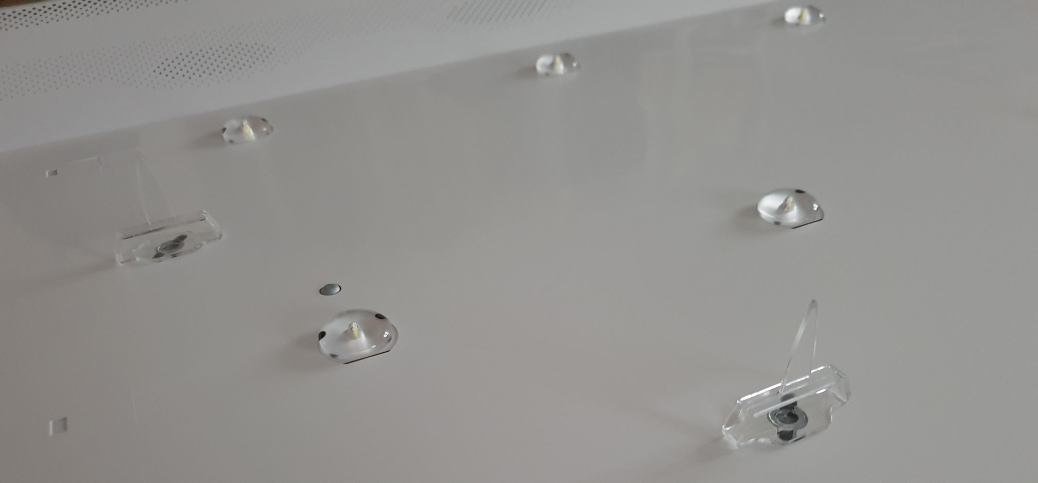
All that work just to get the TV to the original state, with the purple tint. Time to finally remove the panel and replace the backlight.
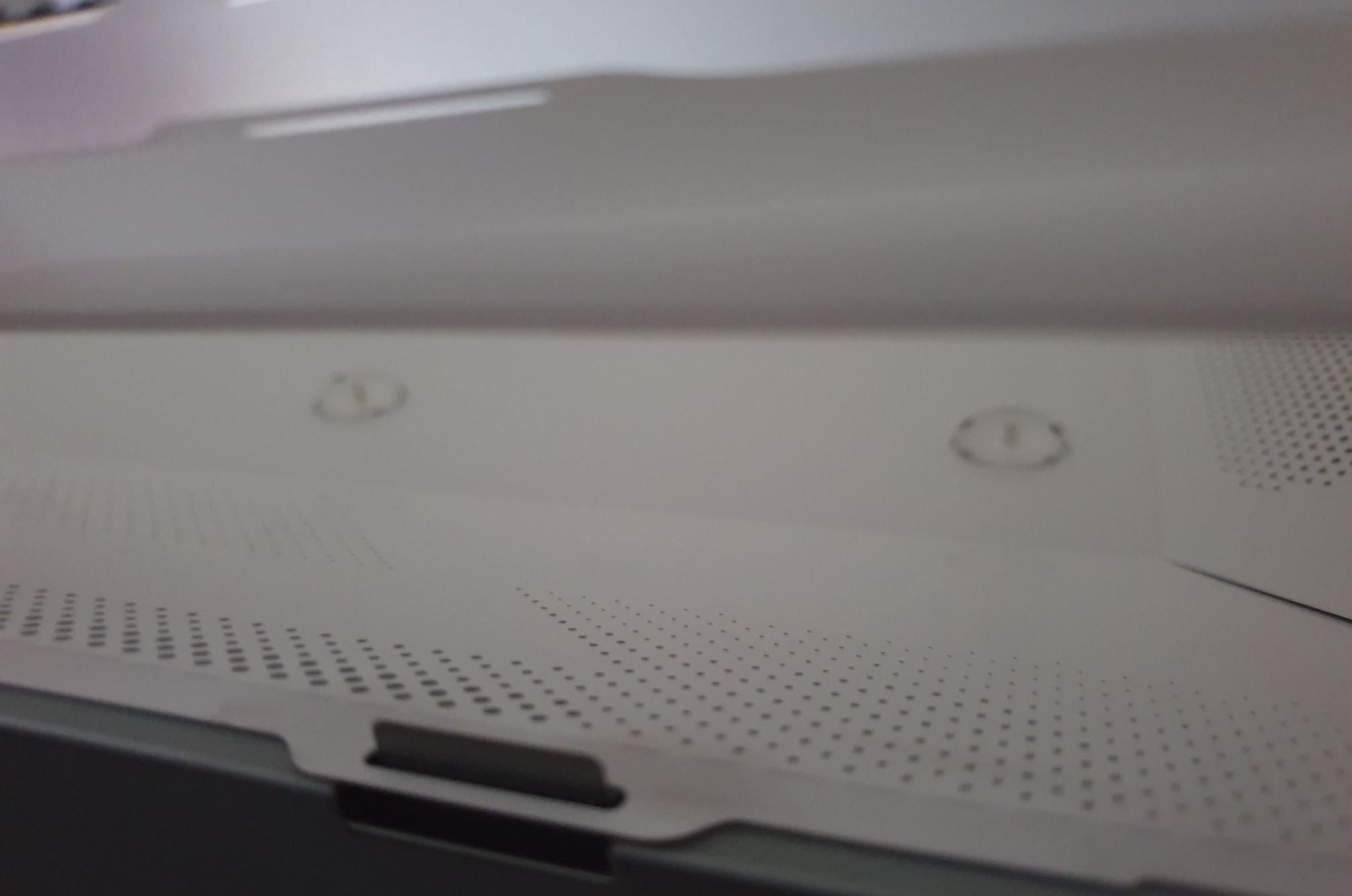
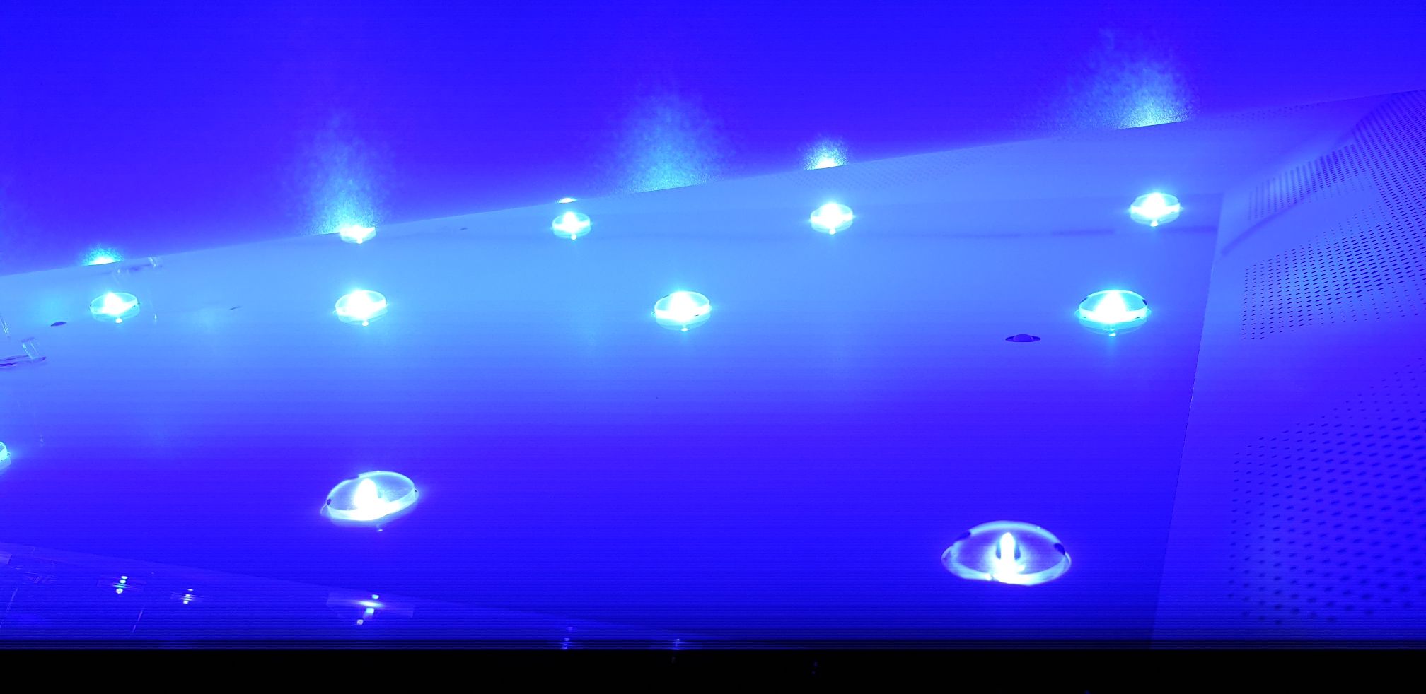
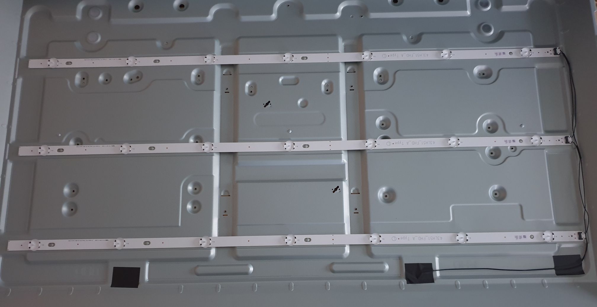
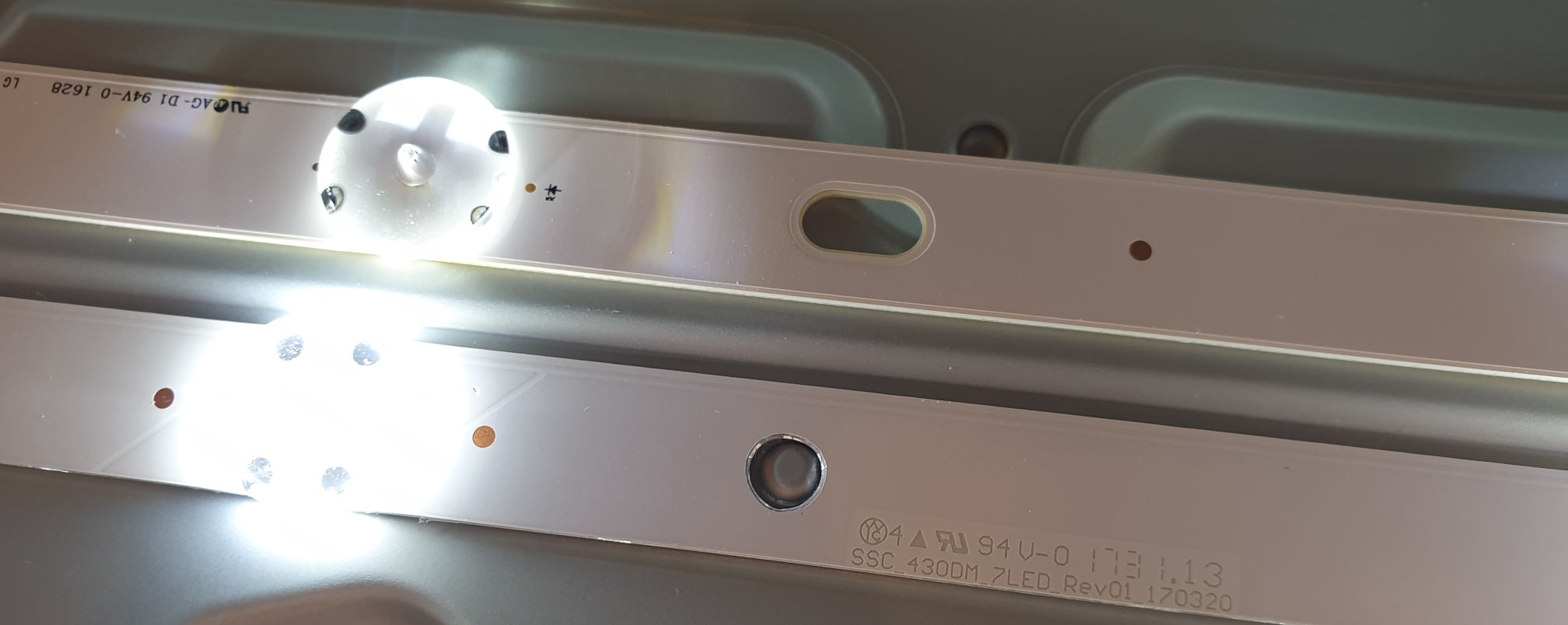
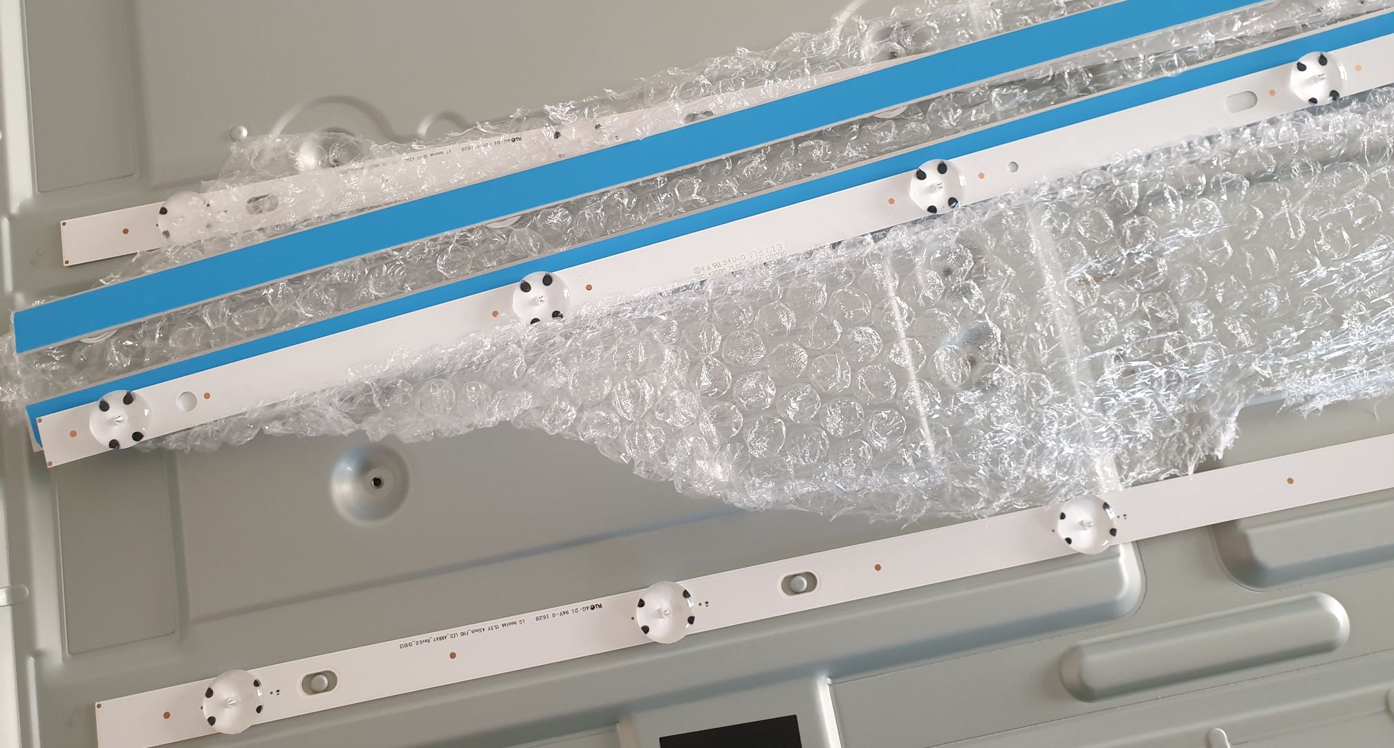
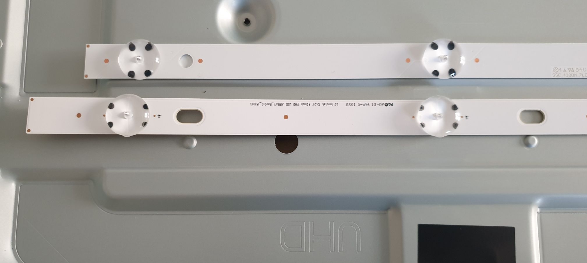
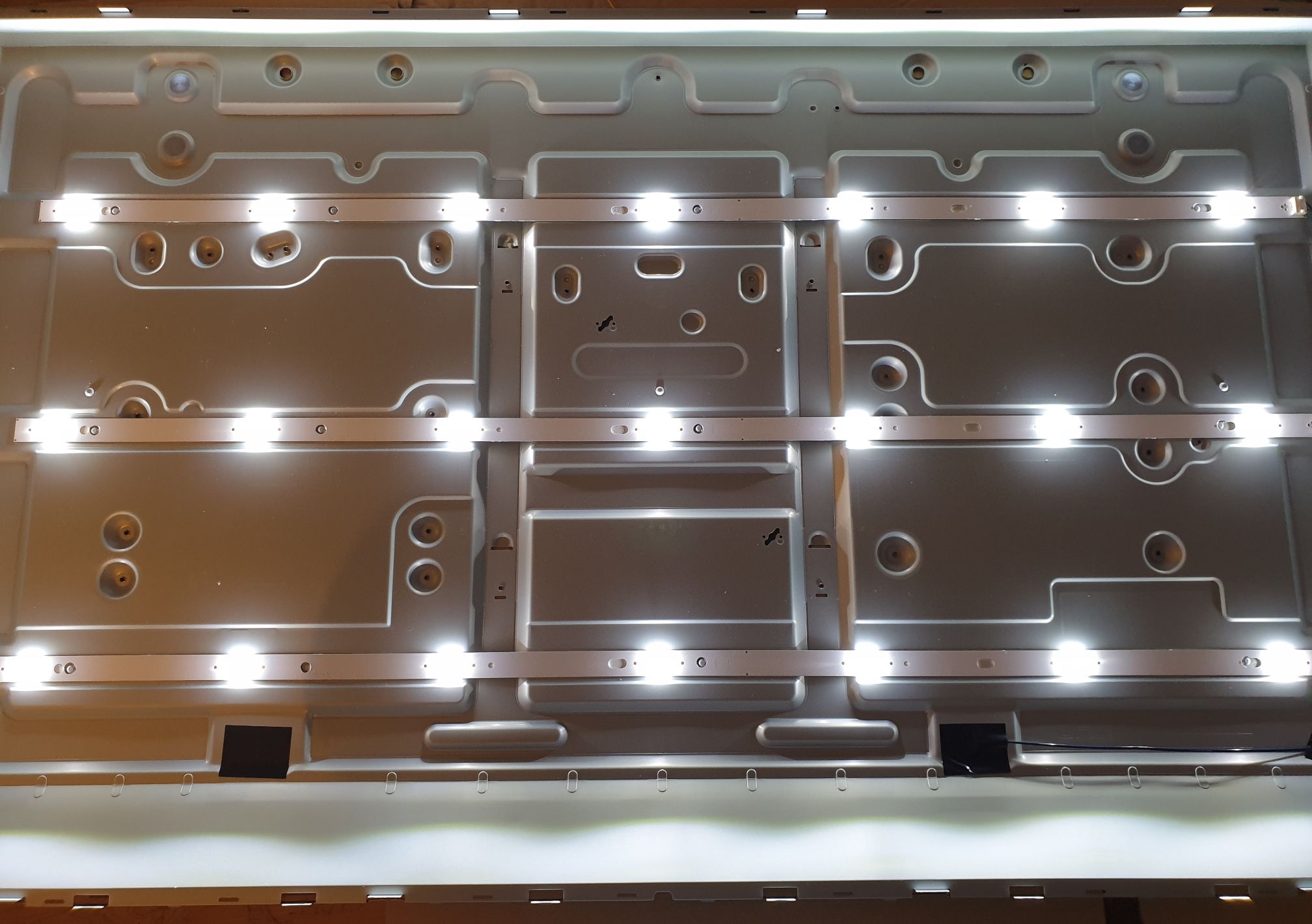
Ended up ordering the new strips from AliExpress with shipping from Spain, so they arrived quite quickly. They matched the LED spacings and connections but were slightly shorter, and the alignment holes didn’t match.
I decided to drill new alignment holes after checking that it would not affect the PCB traces (caution was taken to clean the edges and avoid bridges from the traces to the aluminum backing).
Final result
Well, it works. The overall image was good, but it had some issues. For unknown reasons, the panel had a few red lines on the top and a slight greenish tint on the right side.


The greenish tint was kind of a big deal, but seeing that nothing else could be done, I just assembled it all back together.
And everything went back together perfectly. Well, because I used my debug T-CON for VGH fix I could only use one screw to attach it to the back. I also forgot to place the standoffs between the diffuser layers and the backlight, and I was NOT going to disassemble the display again (it didn’t seem to affect the image anyway).
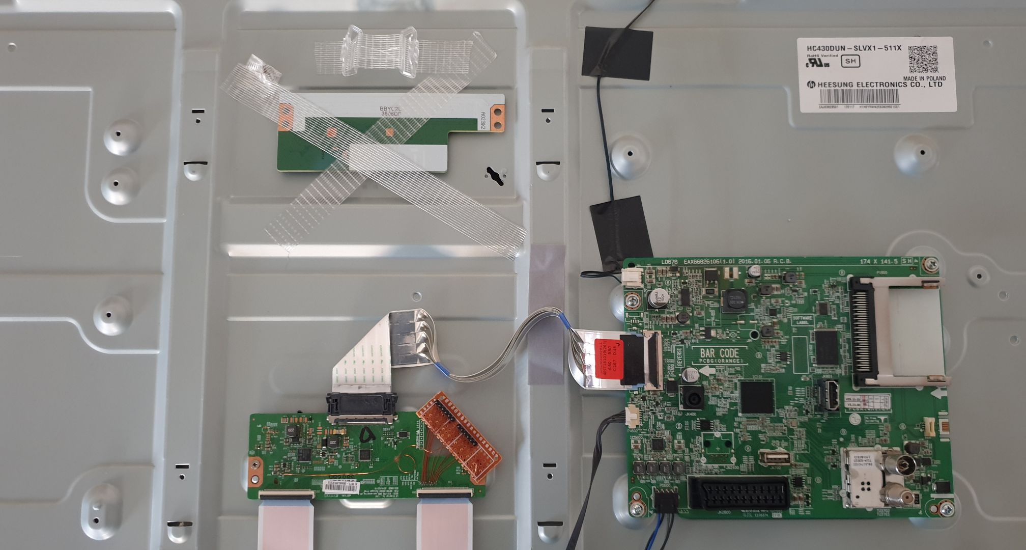
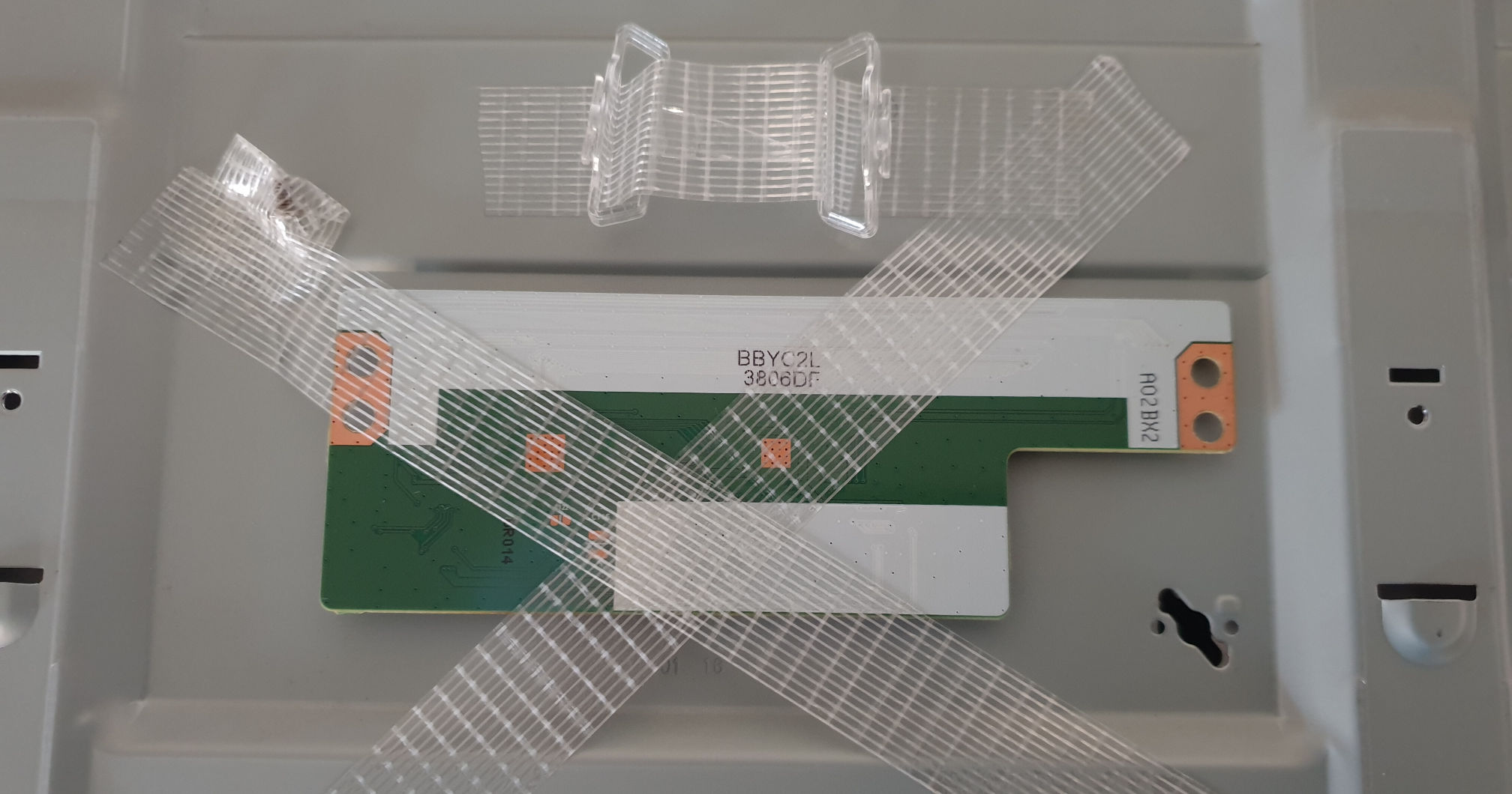
So I just tapped the leftovers and original T-CON board to the back for someone else to find (probably future me if the LEDs fail again).
After a week or so of use, I was surprised that the greenish tint faded, so the final result was quite good. The red pixels also disappeared.

Conclusion
Because of my eagerness to remove the panel, this fix ended up being much more involved than expected. But the final result was good, and I did learn a lot about this kind of repair.
I still don’t fully understand the VGH signal problem. Well, I know that the problem is on the panel itself. The crack goes through an obvious trace. But why are there two complementary VGH signals that flip at such low frequency (freq=206.61mHz, per=4.48s)? Is it an alternative path to drive the transistor gates, maybe related to some balancing?
I was unable to find a patent that shows this VGH_ODD VGH_EVEN duality. But, while writing this post, I did find some references to this kind of fix (hard-wiring VGH) on the web.
That video is a good resource for understanding these signals (but VGH_ODD and VGH_EVEN are not correctly explained on the video, they are not clock signals). All other videos on that channel also provide a lot of valuable information on this topic.
If you have some thoughts on this, send me a message (Email/Twitter).
Extra Images
